In class, Evan introduced some of the basics of programming with you. We began with some simple commands for our BOE-BOT using the BASIC STAMP editor we downloaded from Parallax. The editor used some simple statements like “PULSEOUT” to control external devices from the microprocessor but we spent most of our time typing things like “FOR”, “NEXT”, “PAUSE” and “END” to describe activities internal to the microprocessor. The manufacturer has built it’s own little decoder to transform these commands into the machine language that uses pointers, registers and stacks to carry out these instructions but they accomplish the same thing in the same way: They depend on a strict sequence of actions. We call the rules that constrain and dictate this strict ordering of commands “Programming”.
Most programming begins with a description of the objective of the code. This isn’t always as easy as it sounds and when you’re trying to concisely describe how your robot will throw something at a target you’ll struggle with this. It’s not hard to describe the action and you may even describe a sequence of steps necessary to accomplish it, but unless you think about the sequence with the programming language (the constraints and dictates of the language) you may not be able to implement it. This problem is common to most technological endeavors you will encounter in your career: How to best integrate the hardware and software of a project.
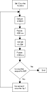
One tool that programmer’s often use is a logic diagram. This uses symbols for “IF”, “SET” etc. that can easily be changed into the programming language, but allow the programmer to visualize the sequential flow of the program to it’s outcome. Let’s take the example of our first program using the Parallax Homework board in which we lit a red led.
 The hardware (circuit on the prototyping board) and the program that made it work couldn’t have been simpler. But look at all the information in the program that the hardware designer might never have thought of :
- How long should the led be lit up?
- How long a pause should we have between lightings?
- How many times should the light be lit up?
By putting together the sequence of events that the microprocessor must do in the accomplishment of the task, the hardware and the software can interact and adjust to make sure the device under development does what its supposed to.
/*
Blink
Turns on an LED on for 300 ms then shuts it off for 300 ms 50 times
*/
// Pin 13 has an LED connected on most Arduino boards.
// give it a name:
int led = 13;
// Set up the counter:
int counter = 0
// the setup routine runs once when you press reset:
void setup() {
// initialize the digital pin as an output.
pinMode(led, OUTPUT);
}
// the loop routine runs 50 times:
void loop() {
For (counter = 1; counter = 50; counter++)
digitalWrite(led, HIGH); // turn the LED on (HIGH is the voltage level)
delay(300); // wait for 300 ms
digitalWrite(led, LOW); // turn the LED off by making the voltage LOW
delay(300); // wait for 300 ms
The code for the Arduino looks different from the BOE-BOT because the BOE-BOT replicates commands written in the language called BASIC and the Arduino has copied command structures that look like the commands in the language called C++. They both translate into roughly the same machine code for pushing and popping bits onto stacks, but the language it’s programmed in looks different.
Recent Comments