This video is from my nephew Alex. At 10, he’ll be starting full time at California State University, L.A. in the fall.
So proud…
Check out all of Alex and Sophie’s videos here and buy their book!
Noema Slur
March 10, 2016
May 5, 2014
L&E Robotics Electronics, FIRST Robotics, FIRST Robotics Mentor Leave a comment

The DigiPen Students won the district event at Shorewood High School. A lot of work and a highly talented team made all the difference in making this a year to remember.
Congratulations to all of you and best of luck in the coming year.
February 1, 2014
L&E Robotics Electronics, FIRST Robotics, FIRST Robotics Mentor Leave a comment
 Today marked a milestone in our progress: The first motorized movement of our robot chassis. Several of the students got a feel for the controls using two joy-sticks coupled to the laptop that interfaced with the robot.

We finally got our parts kit on Thursday and there has been a great deal of progress since then.
There are still many open design questions regarding autonomous portion of the competition (The robot figuring out what to do on its own) and for the actual mechanism for getting the ball and scoring points.
January 19, 2014
L&E Robotics Electronics, FIRST Robotics, FIRST Robotics Mentor Leave a comment

We still don’t have our KoP so everyone divided up into sub-group (Brian calls them “fire teams”) to further plan and develop the design of the robot.
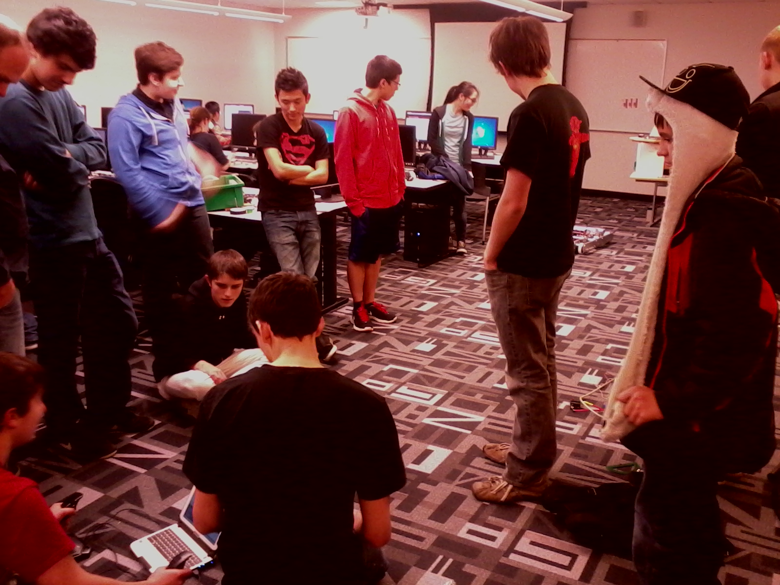
Brian started us off with a brief video covering the electronics of the robot and then asked the electronics fire team to begin planning the layout of components. The programming group met separately (shown in the foreground of the picture) and quickly built a scale mock-up of the field, a white-box of the robot and included all the physics and controls to move the robot around the field. At the upper right you can see L& E’ s own Ian, Bobby and Ian’s dad working on a team logo. Our team also worked on dismantling last year’s bot so that we could have all the parts available for the electronics team to do the layout.
The KoP should be here early next week and we can begin construction in earnest. Bobby has signed up to be a part of the chassis assembly team so he’ll have a lot to contribute once the parts arrive.
Some of the DigiPen students have created a team blog site similar to this one at https://firstrobotics.digipen.edu/ . You are invited to contribute ideas, observations and thoughts about the project on this site.
Want to know more:
January 11, 2014
L&E Robotics Electronics, FIRST Robotics, FIRST Robotics Mentor Leave a comment

We had our first organizing meeting of robotics club today and it was an amazing success. The students not only organized themselves into sub-teams, they also discussed strategy, design and the ordering of some more parts.
L&E was represented by Bobby (shown at the far left of the picture) who will be participating in the chassis construction team. The full roster of teams are:
In addition there was heated discussion about the overall design of the robot. It was quickly decided that our robot would not put anything in the air and would focus on blocking the opposing team’s scores and achieving points by pushing the ball into one of the corner goals.

The basic plan calls for lowering a cross-bar over the ball and then activating a couple of motor-driven wheels at the top of a cross bar long enough to lift the ball off the floor.
The cross-bar would pivot from the center of the robot in order to allow it to capture balls from the back or the front of the robot.
There was a lot of discussion about having 8 or 6 wheels and which should be powered. The club decided that there should be 6 wheels for better traction when blocking opponents and that they should only be 4″ to allow as much room as possible in the robot’s chassis.
The Kit of Parts (KoP) should be arriving soon and we can begin actual construction.
Want to know more:
http://curriculum.vexrobotics.com/curriculum/drivetrain-design/friction-and-traction
http://www.vexrobotics.com/omni-wheels.html
http://firstvideoarchive.com/2009Archive/index.php?dir=Championship_Archimedies/
http://www.usfirst.org/roboticsprograms/frc/technical-resources
January 4, 2014
L&E Robotics Electronics, FIRST Robotics, FIRST Robotics Mentor Leave a comment

The Washington FIRST robotics competition (FRC) was officially launched this morning with the nation-wide broadcast by NASA of the design of the game and an overview of the rules. We met in the gym of the Montlake Terrace High School where they announced that our region now has 879 teams competing in this year’s competition.
Simultaneously, the rules for this years competition were made available. This year’s competition is called “Arial Assist” and comprises moving a 2′ diameter ball between 3 team’s robots (The Alliances will be formed at random during the event) and placing the ball through either a low target (1 point) or a high target (10 points) at either end of a 54′ x 25′ court.

We were then randomly dispersed into class rooms at the High School where we brainstormed ideas for the competition. My session seemed to focus most on interpretations of the rules and the possible strategies you could use based on these constraints.
Others were more technically based and still others that I heard about from our team members focused more on veterans of FRC competitions comparing this competition to previous ones.
These breakouts lasted until about 11:00 and then it was time for teams to get assistance in actually building their kits. Unfortunately we did not get our parts kit today so we took over a class room to strategize and organize a bit.

Our coach Brian Tugade (in the hat) has been in these competitions before and a few of the team were in his class last year. This is an advantage that many teams do not have and should help ease the process.
We decided that each team member should spend the time between now and next Saturday familiarizing themselves with the rules and thinking of ideas for the competition. We’ll meet again at DigiPen next Saturday to put our ideas together and begin the design process. It will be very important to have ALL the L&E students present at that Saturday afternoon meeting.
Want to know more:
http://frc-manual.usfirst.org/
2014 FIRST Kickoff Broadcast is available on Youtube at the FRCTeamsGlobal channel.
Be sure to check out the technical documents section of the usfirst.org site
December 1, 2013
L&E Robotics Electronics, FIRST Robotics, FIRST Robotics Mentor Leave a comment
In class, Evan introduced some of the basics of programming with you. We began with some simple commands for our BOE-BOT using the BASIC STAMP editor we downloaded from Parallax. The editor used some simple statements like “PULSEOUT” to control external devices from the microprocessor but we spent most of our time typing things like “FOR”, “NEXT”, “PAUSE” and “END” to describe activities internal to the microprocessor. The manufacturer has built it’s own little decoder to transform these commands into the machine language that uses pointers, registers and stacks to carry out these instructions but they accomplish the same thing in the same way: They depend on a strict sequence of actions. We call the rules that constrain and dictate this strict ordering of commands “Programming”.
Most programming begins with a description of the objective of the code. This isn’t always as easy as it sounds and when you’re trying to concisely describe how your robot will throw something at a target you’ll struggle with this. It’s not hard to describe the action and you may even describe a sequence of steps necessary to accomplish it, but unless you think about the sequence with the programming language (the constraints and dictates of the language) you may not be able to implement it. This problem is common to most technological endeavors you will encounter in your career: How to best integrate the hardware and software of a project.
One tool that programmer’s often use is a logic diagram. This uses symbols for “IF”, “SET” etc. that can easily be changed into the programming language, but allow the programmer to visualize the sequential flow of the program to it’s outcome. Let’s take the example of our first program using the Parallax Homework board in which we lit a red led.
 The hardware (circuit on the prototyping board) and the program that made it work couldn’t have been simpler. But look at all the information in the program that the hardware designer might never have thought of :
By putting together the sequence of events that the microprocessor must do in the accomplishment of the task, the hardware and the software can interact and adjust to make sure the device under development does what its supposed to.
/*
Blink
Turns on an LED on for 300 ms then shuts it off for 300 ms 50 times
*/
// Pin 13 has an LED connected on most Arduino boards.
// give it a name:
int led = 13;
// Set up the counter:
int counter = 0
// the setup routine runs once when you press reset:
void setup() {
// initialize the digital pin as an output.
pinMode(led, OUTPUT);
}
// the loop routine runs 50 times:
void loop() {
For (counter = 1; counter = 50; counter++)
digitalWrite(led, HIGH); // turn the LED on (HIGH is the voltage level)
delay(300); // wait for 300 ms
digitalWrite(led, LOW); // turn the LED off by making the voltage LOW
delay(300); // wait for 300 ms
The code for the Arduino looks different from the BOE-BOT because the BOE-BOT replicates commands written in the language called BASIC and the Arduino has copied command structures that look like the commands in the language called C++. They both translate into roughly the same machine code for pushing and popping bits onto stacks, but the language it’s programmed in looks different.
November 30, 2013
L&E Robotics Electronics, FIRST Robotics, FIRST Robotics Mentor Leave a comment
 We’ve already been introduced to the BASIC STAMP on our BOE-BOT. A similar chip exists on the BASIC STAMP Homework Board. I pointed this out in class and called it the brains of the robot. In fact it is a form of computer called a microcontroller. A microcontroller differs from the microprocessor in your computer because it has some memory on the chip that allows it to be programmed for a specific task. The clock speeds of microcontrollers are generally slower than for microprocessor but that’s changing fast.
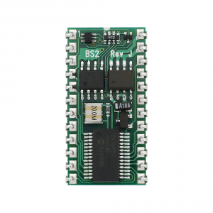
The BASIC STAMP uses a unique programming language that resides in the left-top chip that has BS2 written above it. This actual microprocessor is one manufactured by Microchip called a PIC chip.
When these chips first became available to hobbyists they had to be programmed using a programmer that converted a primative computer language called Assembler language into machine language of 1’s and 0’s.


Once the chip was programmed it could then be moved into the circuit it was intended to control.
Modern microcontrollers like the BASIC STAMP are able to be programmed and operate on a single board that is programmed through a USB port and has it’s input and output pins easily accessed through headers.
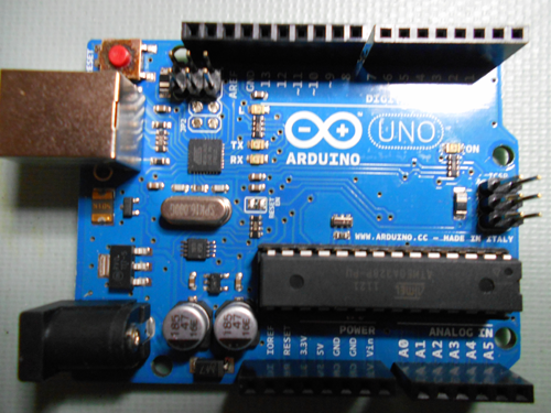 At DigiPen, our coach, Brian, prefers to use another microcontroller called the Arduino. This microcontroller is extremely popular among hobbyists right now and you will undoubtedly see many at the FIRST competition.
It uses a USB port (large metal cube on the far left) to program it. The actual chip that powers it is made by Amtel (the long chip at the bottom) and clocks even faster than the BASIC STAMP (the crystal clock is the oval can on the mid-left side of the board).
Part of their popularity is due to the fact that the manufacturer has produced a number of interface boards called “shields” that clip onto the headers. These can be used for wireless communications, motor control or any other interface you might need for your robot with little need for peripheral chips or discrete components to support it.
The LEGO robotics kit we have uses 3 Amtel microprocessors. One for communication, one is the main microprocessor and the last one is dedicated to motor control. Of all the microcontrollers we’ll be using it is, by far the most advanced. Fortunately the interface only gives you a few outputs and inputs so you don’t have to consult the technical documents for these microcontrollers to make it work.
Understanding the internal workings of microcontrollers is helpful but not necessary to making a robot work. What is important is to understand what we’re talking about when we refer to registers, stacks or memory address pointers that our program affects.
The microprocessor depends on a strict sequence of events that transition with each pulse of the clock. The first thing a microprocessor does is to “fetch” the instruction it is to execute from the program cache one line at a time. Once the instruction has been read, it is interpreted by the “decoder unit” inside the microchip. The code can ask for input from one of the microcontroller’s ports, perform an arithmatic function, or place something in temporary memory. Each of these activities is performed using a bucket of memory for the accumulation of operations, a bucket for what’s called the base, a code bucket and a memory bucket for data. These are called the Ax, Bx, Cx and Dx registers. In addition to these the manufacturer of the chip will have a bunch of “Special Purpose Registers” (SPRs) that you can’t change but take memory. Any of these is manipulated by the code sequence by refering to pointers. Pointers are simply the memory address that contains the data the program needs. The pointer moves, pushes or pops data on and off portions of temporary memory called stacks until another call is made to overwrite the memory used in the last operation.
Microcontrollers have varying amounts of on-board memory divided into RAM (random access memory) and programmable memory for holding constants or tables you’ll instruct code to look at. If your robot is to do anything spectacular, however, you’ll eventually need to access external memory using one of the microcontroller’s ports.
Want to know more
November 30, 2013
L&E Robotics Electronics, FIRST Robotics, FIRST Robotics Mentor Leave a comment
As we said at the outset, we count on chips that have most of the discrete components incorporated on them so most robot circuitry is dominated by little black integrated circuits (ICs) sometimes called bugs.
Each IC has an even number of pins sticking out it’s side that correspond to some input or output of a miniature circuit housed inside the chip. On most of chips there is a dot or an indentation over the pin that is labeled as pin 1 and the pins are identified by counting from the first pin, down the left side of the chip and then following the pins in counter-clockwise around the chip.
To find out what the other pins do and how to use the chip, each manufacturer publishes technical specifications for the chips they manufacture. These are freely available on-line and often include schematics of the useful circuits that include the chip.
In the last blog we saw how a single chip could replace 4 transistor switches to make an H-Bridge for controlling the motors on our robot. There are other chips that are very useful in robotics as well.
Among the most useful of all chips is the Operational Amplifier or Op Amp. These amplify small voltages in a way that can be controlled by setting the amplifier’s “gain”.
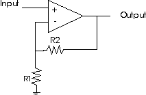
The op amp is so prevalent in electronics that it deserves it’s own symbol shown as the triangle in the schematic drawing. There are positive and negative inputs, an output pin. When there are no resistors connected to the op amp it outputs the voltage that is the difference between the + and – input voltages. This is called a comparator and can be very useful if a robot has sensors that are trying to see if one thing is “hotter”, “brighter”, “darker” etc. than some reference voltage.
With the resistors added the ouput voltage equals 1+ R1/R2. If the input voltage were 1.5 volts and the resistors were both 220 Ohms, what would the output voltage be?
Another common chip you’ll see in robots are Analog to Digital converters (A/D Converters). These devices take an analog signal from a sensor of light, temperature, sound etc. and turn it into a digital number that a computer can read. There are Digital/Analog converters too and they’re also used in robots but not as often as Analog to Digital. In order for the digital signal (remember that a digital number is a series of “1”s and “0”s) it must either be sent to the BASIC STAMPS’s input as a series of 1’s and 0’s on a single wire (we call this “serial input”) or on a bunch of wires each representing one place in the binary number system we learned about earlier (we call this “Parallel input”) These are used so often that most robotics microcontrollers have integrated the A/D converters for you.
A final typical chip you’ll be introduced to in robotics are voltage regulators. You will seldom see a robot that only uses one voltage for everything. Usually the motors have one voltage, the microcontroller has another and the mechanics for grabbing, throwing or other uses operate on a third voltage. Making sure you have enough of the right voltage is an important step in the design of your robot and you’ll want to make sure the voltage and current you supply is not too much and not too little for the task at hand.
Want to know more
http://www.youtube.com/watch?v=K03Rom3Cs28
https://learn.sparkfun.com/tutorials/analog-to-digital-conversion
http://www.youtube.com/watch?v=KZsyMnJ1NSs
November 29, 2013
L&E Robotics Electronics, FIRST Robotics, FIRST Robotics Mentor Leave a comment
Transistors are in the family of devices called “semiconductors” which have the unique property of making insulators into conductors. The most common of these insulators is silicon with impurities in it that allow this transformation to occur.
A transistor has three leads:

When current is supplied to the base it allows current to flow from the collector to the emitter, otherwise no current flows past the base.

Transistors come in two flavors PNP and NPN (as shown above) which are symbolized with the arrow pointing to the “N”.
The NPN shown on the far right is, by far, the most common sort of transistor.
In class we saw how we could program the BASIC STAMP chip to light an LED light using just the 1.5 volt signal coming from the STAMP, but what if the light took more than 1.5 volts or there was a chance of some voltage coming backwards from a circuit into the STAMP’s output port?
One way to handle these questions might be to isolate the “on”/”off” signal with a transistor switch. To do this we would simply connect the STAMP’s output to the base of an NPN transistor and the input to the lamp or other thing we’re switching on to the emitter with it’s power source connected to the collector.
In the last blog we made one of the most used circuits using resistors; the voltage divider. But in robotics no circuit is more common than the transistor switch and it’s close cousin the emitter-follower.

The transistor switch requires a transistor, a power supply connected to a load (a circuit to do something like light up an led) and a power source to send a positive voltage from the BASIC STAMP.

Similar to the transistor switch is a circuit called the emitter-follower which connects the circuit to the emitter side of the transistor.
One of the most common motors used in robots are DC motors that require a steady DC current rather than the pulsed signals of a servo or stepper motor. In order to reverse these motors you have to reverse the polarity (exchange the + an – voltages) on the motor. A common way this is accomplished in robots is through what’s called an “H-Bridge” because it’s schematic diagram looks roughly like the capital letter “H”.
 To make the motor run forward we switch on the high-side-left switch and the low side right switch. To make it run backwards we switch on the high-side-right switch and the low-side-left switch.
If we have two motors (two wheels on our robot) we can make one move forward and the other backward (or just slower) to make the robot turn.
We can replace the mechanical switches in the diagram with transistor switches in order to accomplish the same thing but by using >.6 volts on the base of any of the 4 transistor switches.
This has become so common that we now have chips with a full H-Bridge contained in them and we only need to hook up the pins to the correct motor pole, battery or output from our BASIC STAMP.
Want to know more
http://techhouse.brown.edu/~dmorris/projects/tutorials/transistor.switches.pdf
http://www.ermicro.com/blog/?p=423

Recent Comments