Home

13. Technology in robotics: Microprocessors

Leave a comment

BS2-ICWe’ve already been introduced to the BASIC STAMP on our BOE-BOT.  A similar chip exists on the BASIC STAMP Homework Board.  I pointed this out in class and called it the brains of the robot.  In fact it is a form of computer called a microcontroller.  A microcontroller differs from the microprocessor in your computer because it has some memory on the chip that allows it to be programmed for a specific task.  The clock speeds of microcontrollers are generally slower than for microprocessor but that’s changing fast.

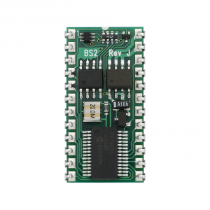
The BASIC STAMP uses a unique programming language that resides in the left-top chip that has BS2 written above it.  This actual microprocessor is one manufactured by Microchip called a PIC chip.

When these chips first became available to hobbyists they had to be programmed using a programmer that converted a primative computer language called Assembler language into machine language of 1’s and 0’s.

picstartpicrun

Once the chip was programmed it could then be moved into the circuit it was intended to control.

Modern microcontrollers like the BASIC STAMP are able to be programmed and operate on a single board that is programmed through a USB port and has it’s input and output pins easily accessed through headers.

Arduino UNO
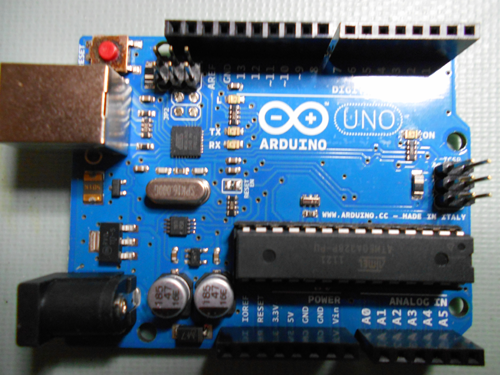
At DigiPen, our coach, Brian,  prefers to use another microcontroller called the Arduino.  This microcontroller is extremely popular among hobbyists right now and you will undoubtedly see many at the FIRST competition.  

It uses a USB port (large metal cube on the far left) to program it.  The actual chip that powers it is made by Amtel (the long chip at the bottom) and clocks even faster than the BASIC STAMP (the crystal clock is the oval can on the mid-left side of the board).

Part of their popularity is due to the fact that the manufacturer has produced a number of interface boards called “shields” that clip onto the headers.  These can be used for wireless communications, motor control or any other interface you might need for your robot with little need for peripheral chips or discrete components to support it.

The LEGO robotics kit we have uses 3 Amtel microprocessors.  One for communication, one is the main microprocessor and the last one is dedicated to motor control.  Of all the microcontrollers we’ll be using it is, by far the most advanced.  Fortunately the interface only gives you a few outputs and inputs so you don’t have to consult the technical documents for these microcontrollers to make it work.

Understanding the internal workings of microcontrollers is helpful but not necessary to making a robot work.  What is important is to understand what we’re talking about when we refer to registers, stacks or memory address pointers that our program affects.

The microprocessor depends on a strict sequence of events that transition with each pulse of the clock.  The first thing a microprocessor does is to “fetch” the instruction it is to execute from the program cache one line at a time.  Once the instruction has been read, it is interpreted by the “decoder unit” inside the microchip.  The code can ask for input from one of the microcontroller’s ports, perform an arithmatic function, or place something in temporary memory.  Each of these activities is performed using a bucket of memory for the accumulation of operations, a bucket for what’s called the base, a code bucket and a memory bucket for data.  These are called the Ax, Bx, Cx and Dx registers.  In addition to these the manufacturer of the chip will have a bunch of “Special Purpose Registers” (SPRs) that you can’t change but take memory.  Any of these is manipulated by the code sequence by refering to pointers.  Pointers are simply the memory address that contains the data the program needs.  The pointer moves, pushes or pops data on and off portions of temporary memory called stacks until another call is made to overwrite the memory used in the last operation.

Microcontrollers have varying amounts of on-board memory divided into RAM (random access memory) and programmable memory for holding constants or tables you’ll instruct code to look at.  If your robot is to do anything spectacular, however, you’ll eventually need to access external memory using one of the microcontroller’s ports.

Want to know more

http://www.pictutorials.com/what_is_microcontroller.htm

http://srinivasarao.webs.com/micro-cntrl.pdf

Advertisement

12. Technology in robotics: Useful Chips

Leave a comment

As we said at the outset, we count on chips that have most of the discrete components incorporated on them so most robot circuitry is dominated by little black integrated circuits (ICs) sometimes called bugs.

Each IC has an even number of pins sticking out it’s side that correspond to some input or output of a miniature circuit housed inside the chip.  On most of chips there is a dot or an indentation over the pin that is labeled as pin 1 and the pins are identified by counting from the first pin, down the left side of the chip and then following the pins in counter-clockwise around the chip.

To find out what the other pins do and how to use the chip, each manufacturer publishes technical specifications for the chips they manufacture.  These are freely available on-line and often include schematics of the useful circuits that include the chip.

In the last blog we saw how a single chip could replace 4 transistor switches to make an H-Bridge for controlling the motors on our robot.  There are other chips that are very useful in robotics as well.

Among the most useful of all chips is the Operational Amplifier or Op Amp.  These amplify small voltages in a way that can be controlled by setting the amplifier’s “gain”.

opamp

The op amp is so prevalent in electronics that it deserves it’s own symbol shown as the triangle in the schematic drawing.  There are positive and negative inputs, an output pin.  When there are no resistors connected to the op amp it outputs the voltage that is the difference between the + and – input voltages.  This is called a comparator and can be very useful if a robot has sensors that are trying to see if one thing is “hotter”, “brighter”, “darker” etc. than some reference voltage.

With the resistors added the ouput voltage equals 1+ R1/R2.  If the input voltage were 1.5 volts and the resistors were both 220 Ohms, what would the output voltage be?

Another common chip you’ll see in robots are Analog to Digital converters (A/D Converters).  These devices take an analog signal from a sensor of light, temperature, sound etc. and turn it into a digital number that a computer can read.  There are Digital/Analog converters too and they’re also used in robots but not as often as Analog to Digital.  In order for the digital signal (remember that a digital number is a series of “1”s and “0”s) it must either be sent to the BASIC STAMPS’s input as a series of 1’s and 0’s on a single wire (we call this “serial input”) or on a bunch of wires each representing one place in the binary number system we learned about earlier (we call this “Parallel input”) These are used so often that most robotics microcontrollers have integrated the A/D converters for you.

A final typical chip you’ll be introduced to in robotics are voltage regulators.  You will seldom see a robot that only uses one voltage for everything.  Usually the motors have one voltage, the microcontroller has another and the mechanics for grabbing, throwing or other uses operate on a third voltage.  Making sure you have enough of the right voltage is an important step in the design of your robot and you’ll want to make sure the voltage and current you supply is not too much and not too little for the task at hand.

Want to know more

http://www.youtube.com/watch?v=K03Rom3Cs28

https://learn.sparkfun.com/tutorials/analog-to-digital-conversion

http://www.youtube.com/watch?v=KZsyMnJ1NSs


11. Electronics in robotics: Transistors

Leave a comment

Transistors are in the family of devices called “semiconductors” which have the unique property of making insulators into conductors.  The most common of these insulators is silicon with impurities in it that allow this transformation to occur.

A transistor has three leads:

  • The Collector
  • The Emitter, and
  • The Base

npn

When current is supplied to the base it allows current to flow from the collector to the emitter, otherwise no current flows past the base.

transistor-npn-pnp-symbols

Transistors come in two flavors PNP and NPN (as shown above) which are symbolized with the arrow pointing to the “N”.

The NPN shown on the far right is, by far, the most common sort of transistor.

In class we saw how we could program the BASIC STAMP chip to light an LED light using just the 1.5 volt signal coming from the STAMP, but what if the light took more than 1.5 volts or there was a chance of some voltage coming backwards from a circuit into the STAMP’s output port?

One way to handle these questions might be to isolate the “on”/”off” signal with a transistor switch.  To do this we would simply connect the STAMP’s output to the base of an NPN transistor and the input to the lamp or other thing we’re switching on to the emitter with it’s power source connected to the collector.

In the last blog we made one of the most used circuits using resistors; the voltage divider.  But in robotics no circuit is more common than the transistor switch and it’s close cousin the emitter-follower.

trswitch2

The transistor switch requires a transistor, a power supply connected to  a load (a circuit to do something like light up an led) and a power source to send a positive voltage from the BASIC STAMP.

EF

Similar to the transistor switch is a circuit called the emitter-follower which connects the circuit to the emitter side of the transistor.

One of the most common motors used in robots are DC motors that require a steady DC current rather than the pulsed signals of a servo or stepper motor.  In order to reverse these motors you have to reverse the polarity (exchange the + an – voltages) on the motor.  A common way this is accomplished in robots is through what’s called an “H-Bridge” because it’s schematic diagram looks roughly like the capital letter “H”.

basic-bridgeTo make the motor run forward we switch on the high-side-left switch and the low side right switch.  To make it run backwards we switch on the high-side-right switch and the low-side-left switch.

If we have two motors (two wheels on our robot) we can make one move forward and the other backward (or just slower) to make the robot turn.

We can replace the mechanical switches in the diagram with transistor switches in order to accomplish the same thing but by using >.6 volts on the base of any of the 4 transistor switches.

This has become so common that we now have chips with a full H-Bridge contained in them and we only need to hook up the pins to the correct motor pole, battery or output from our BASIC STAMP.

Want to know more

http://techhouse.brown.edu/~dmorris/projects/tutorials/transistor.switches.pdf

http://www.ermicro.com/blog/?p=423

http://www.instructables.com/id/H-Bridge-on-a-Breadboard/

http://www.ti.com/lit/ds/slvsar1c/slvsar1c.pdf

10. Electronics in robotics: Ohm’s Law

Leave a comment

In an earlier blog we saw how the relationship between current (I), voltage(V) and resistance(R) combined into one of the most important identities in electronics called Ohm’s law.  To review, the current is the speed with which the electrons are allowed to flow, the voltage is the energy exerted on the electrons to flow and resistance is any reduction in the ability of the electrons to flow.

ohms-law-illustrated

Changing any one of the three will change the other two in a way that makes it easy to apply algebra to.  If the resistance increases, the amps can’t move as fast (current decreases) and the ratio of the volts to current increases.

Similarly, in order for the current to increase, either the voltage has to be stronger than the resistance or the resistance has to decrease.

We write this relationship as

R=V/I

I=V/R

V=I x R

The first component that we looked at in an earlier blog was the resistor which obviously has to do with Ohm’s law because it’s sole job is to increase resistance.  

If we put a 100 Ohm resistor across a battery’s terminals the voltage from the battery will be 1.5 volts but the current will be equal to the voltage divided by the resistance or 15 milliamps (15×10-3Amps)

ohms1ohms2

It’s worth noting that the current would be the same on either side of the resistor.

But what if we want to vary the voltage? One of the most frequently used circuits in electronics is the voltage divider which makes use of Ohms law and the fact that if you put two resistors in a series, the total resistance will be the sum of the two resistor’s ohm values or simply R1 + R2.

divider

According to Ohm’s Law, the current I will be the Voltage divided by the resistance.  Since there are two resistors this will be the sum of the two resistors you see in the denominator and the voltage in the numerator.  Again, according to Ohm’s Law in order to get the voltage we multiply the current by the resistance in the second resistor  which you see in the numerator of the formula in the drawing.

Suppose we had a 12 volt battery (common in robots) and two 100 ohm resistors in parallel like in the drawing above.  How much voltage would we have at the output of the voltage divider?

Want to know more

http://www.youtube.com/watch?v=-mHLvtGjum4

8. Mathematics in robotics: Units of Measure

Leave a comment

Most of us are used to single measurements of everyday items.  A ruler can give us linear measures in units of inches or centimeters; a measuring cup can give us volume measures in units of cups or fluid ounces.  But when you’re measuring electrons in a circuit your measuring something really small!

For example, your standard car speakers will require the radio to pump 104,000,000,000,000,000,000 electrons per second…well that’s just silly! Even if it were helpful to know how many electrons it took to power my sub-woofer it would be easier to write as “104-followed-by-18-zeros” or in scientific notation as 104 x 1018. But there are many cases where we need a unit of measure that counts a lot of electrons at once. Using some very clever experiments, people decided that the count of 6.241×10¹⁸  electrons could be called “one coulomb” and that moving that many electrons past a point in one second would be called “one ampere”.

1 Ampere = 1 coulomb / 1 second

Whenever we come across a measurement that includes the word “per” or “rate” we should use a division sign to symbolize it.  Thus “miles per gallon” becomes miles/gallon and “miles per hour” becomes mi./hr. Since ampere’s or amps are measured in units per second, it is a measure of the speed at which the electrons are flowing, not the number of electrons that are present.  Actually the number of electrons present won’t matter in electronics.  Every helium atom has two electrons but I guarantee you won’t charge your smartphone by plugging it into a helium balloon. The only way to get those electrons to flow is if there are more electrons on one side of the circuit than the other.  The difference between the two is measured in volts.  This is a very different measure than the one for current (amperes) which measured the velocity of electrons in a wire.  Volts are a measure of force (you can think of it as pressure) on the electrons to move.  This force or energy that results from having more electrons on one pole than the other is measured in a unit called Joules.  The number of joules per coulomb (energy per number of electrons) is what we refer to as volts.

1 volt = 1 joule/1 coulomb

We now have two measurements of electricty; the ampere as the unit of measure of current (symbolized as I) and volts as the measure of voltage (symbolized as V).  But the only time anything interesting happens is when we pass the current and the voltage through something (e.g. a light bulb, a radio or a computer)  What we’re changing is the amount of each that travels through a conductor.  Whenever we change the ability of a conductor we call it the conductor’s “resistance”.  We measure resistance in units called “ohms” (symbolized as  Ω) and an ohm is measured in terms of volts per amp or

1 Ohm = 1 Volt / 1 Ampere

Resistance is the third leg of the fundamental law for all electronics.  Just like the example we gave earlier about π , the combination of resistance, current and voltage can describe everything interesting that’s happening in a circuit.

Besides what’s happening in a circuit, FIRST robotics will be concerned with how much the robot weighs, how long the battery can last and how much things cost.  We’ll have to constantly be measuring, inventorying, estimating and reporting on measured quantities.

When we’re figuring out what to buy for our robot we’ll have to stick to the budget that FIRST has given us (I think we can add up to $400 to the $5,000 in parts that FIRST will give us).  Budgeting requires that we estimate how much each part will cost and make sure we don’t use all of the money before we’ve purchased everything we need.  How might the notion of budgeting apply to a circuit?  Can you use up electricity?

Want to know more

http://www.chem.tamu.edu/class/fyp/mathrev/mr-scnot.html

http://www.convert-me.com/en/

http://www.youtube.com/watch?v=kQamA_mRhqA

9. Electronics in robotics: Discrete components

Leave a comment

At first glance you might think building a robot will require a deep understanding of electronics but it actually relies on a lot of the electronics we need being self contained in little chips on a circuit board.  All we really need to do in robotics is to connect the chip’s pins to the right inputs and outputs in order to make the robot do what we want it to.  Sometimes, however, we can’t simply connect things together or we’ll destroy a chip and often it helps to know the function of each chip in order to better diagnose what might go wrong with the robot during a competition.

Let’s begin with the basic notion of a circuit.  A circuit describes the condition where electric current (remember that current is the flow of electrons) flows from a source, through the devices in the circuit and returns to the source’s other pole.  This seems pretty intuitive but it’s important to understand that you can’t do much with current that goes to something but you can do a lot when it flows through it and into a ground.

Discrete components

Resistors

  • Unit of measure: Ohms
  • Types: Surface Mount, carbon, foil.
  • What they do: change the ratio of voltage to current in a circuit
  • Symbol resistor
  • what they look like

resistors

From top to bottom

Surface mount, DIP chip, carbon, foil, precision foil

.

.

.

.

Capacitors

  • Unit of measure: Farads (although its usually microfarads or picofarads)
  • Types: surface mount, ceramic, tantalum, poly, electrolytic
  • What they do: They’re little reservoirs that can hold a finite amount of electricity.
  • Symbol:cap
  • What they look like

capacitors

In order from left to right

Ceramic, tantalum, poly, Electrolytic (I’m out of surface mount caps but they look just like the surface mount resistors).

.

.

.

.

Diodes

  • Unit of measure: Two numbers.  The high voltage is the reverse voltage limit that will fry your diode and the small voltage is the voltage drop from the anode to the cathode.
  • Types: Zener, Schottky,  Light emitting, rectifier, thyristor
  • What they do:  Basically they’re a one-way valve for electricity.  They’re most often used to flatten a sign wave or oscillating current.
  • Symbol: diode
  • What they look like

diodes

From top to bottom:

Surface mount, Zener, rectifying

.

.

.

.

.

Transistors

  • Unit of measure: Max voltage between the emitter and the collector, current gain to the emitter (called the beta),
  • Types: surface mount, NPN, PNP, Darllington, Field Effect, etc.
  • What they do: most people use them as a switch but they actually act as a current amplifier.
  • Symbol: transistor
  • What they look like

transistors

From left to right:  These are all NPN transistors of increasing power.

Surface mount, TO-92 package, TO-220 package, TO-3 package

.

.

.

.

Crystals

  • Units of measure: Cycles per second or Hertz (1 Hz=1 cycle per second)
  • Types: crystal, crystal with cap included
  • What they do:  These are the “Pulse” of the microcontroller we spoke about in the 4th blog but they’re also used in R/C in order to establish the radio frequency you’ll be using to control your robot.
  • Symbol: crystal
  • What they look like:

crystals

.

.

.

.

.

.

Want to know more

This about the coolest way I know to learn basic electronics: http://www.falstad.com/circuit/e-index.html

7. Mathematics in robotics: Number Systems

Leave a comment

The Piraha people of the Amazon only have 3 numbers: 1, 2 and all-numbers-more-than-2.  That’s really all the data they ever need to represent but most other cultures have found it necessary to communicate more information (data) than that and have developed number systems that allow them to do that.  These usually start with something like notches on a stick or stone counters.  The problem is that these get longer with each one you add so most people’s numbering systems began to count using a system that got longer by multiples of 10.  In this decimal system (deci- is Greek for tenth) the first place is reserved for counting the number of 1’s, the position next to that is reserved for counting the number of 10’s, next is reserved for the number of 100’s (10×10), next 1,000’s (10x10x10) etc.  Because digital information comes to us as pulses of “on” and “off” we’ve kinda had to go backwards from the innovations of the decimal system.  The easiest way to represent digital information (data) is by reserving each place in the number represent a multiple of 2.  So the first place represents the number of 1’s just like the decimal system but instead of the next place holding 10’s it holds the 2’s and the third place is for holding 4’s (2×2) the fourth for holding 8’s (2x2x2) etc.  We call this system of number binary.

The decimal number 7 would be written as 111 in binary and the number 5 as 101.  How would you write the decimal number 9 in binary?

Handling a string of 1’s and 0’s is fine for a computer, but when we’re typing computer code and we want to input a big binary number we’d end up typing a long string of 1’s and 0’s.  Once again people had to come up with a way to write shorter representations of the data.  In the decimal system there’s one other convention that I forgot to mention…we use commas after every 3 place holders in the number (1,000’s, 1,000,000’s etc.).  This makes it easier for us to count really big numbers.  The first innovation that took place in our use of binary numbers in computers was to create a system like the use of comma’s in the decimal system so we decided that after 3 places in the binary system (which counts 8 numbers or “bits” as their called in the binary system) we’d call it a “byte”.  A number system that added a place after every multiple of 8 would reserve the first place for 1’s, the second place for 8’s, the third for 64’s etc.  We call this the octal system of numbers.  In this system of numbers 111 would be equal to the decimal number 73 (64+8+1).  We decided to write this system by adding the alphabet to our decimal system as  0,1,2,3,4,5,6,7.  The decimal number 74 would be 112.  How would you write 80 in octal notation?

Finally, the system used in most programs combines a lower byte (1111) and an upper byte (1111) into number system called the hexidecimal system of numbers.  It borrows letters from the alphabet to enable counting from 0 to 16 in the first position:  0,1,2,3,4,5,6,7,8,9,a,b,c,d,e,f.  So the number ff written in Hexidecimal would equal 255 (240+15).  In Binary this would be equal to 1111 1111.

Numbering systems are useful ways for representing data but there are other ways we use communicate information that are not digital.  Can you think of any other systems of communication that use something other than the decimal system which is based on the number 10?

Want to know more

http://www.engineeringtoolbox.com/binary-octal-hexadecimal-numbers-d_1802.html

http://www.dcs.bbk.ac.uk/~roger/binhex.html

6. Mathematics in robotics

Leave a comment

Mathematics is one of many tools we’ll use in robotics.  Now when most of us are using a hammer we aren’t thinking to ourselves “I am using a hammer.  I am striking this nail with a hammer.  The hammer is hitting the nail…”  but when we’re taught mathematics we spend a lot of time focused on the tools of mathematics and that can be boring and frustrating.  With enough practice, however, we get comfortable using the hammer and are thinking about the outcome of our hammering, we’re using it in the context of some larger construction that we have in mind.  The same thing goes for math.  Math is only useful when we’re using it to build and discover.

I think everyone must have felt a chill when they first learned that the circumference of any circle, no matter how big, divided by its diameter always equaled 3.14159… Wow! How did that happen?  Is there any case that isn’t true?  Are there any other things in the universe that I can understand that rely on a constant like this?  Discoveries like this are still happening even today and we use those discoveries in our technologies and engineering.  In fact most modern technologies are completely dependent on those discoveries.

We won’t be using much math in this competition, but knowing how some basic tools can be used to make a better robot are as important as knowing how to use a screwdriver or a remote control console.  The basic tools are the ability to count, the ability to use arithmetic and the ability to find unknowns in an equation (algebra).  In order to master this tool I suggest we approach it like we would a new language.  First say it in english

“you can wrap 3.14 can lids around a can (assuming all three came from the same can)”,

then draw it as a picture,

pi

and then write it in the alphabetic symbols of that language

piequ

Want to know more:

http://www.geom.uiuc.edu/~banchoff/Flatland/

http://www.education.rec.ri.cmu.edu/downloads/education_standards/standards_menus/STEM%20lessons%20for%20Immersion%20Units.pdf

5. Logic

Leave a comment

Logic is used in the courtroom to structure sound arguments and can be used to deduce or induce a truth we’re grappling but in electronics and programming it’s the basis of how we put things together.

gates

In class I showed two circuits that would turn on a light using a battery and two switches.  The AND set of switches (AND Gate) requires that both of the switches be on in order for the light to turn on.  Then we built one using a breadboard and an LED with two switches

The OR gate only required that one of the switches was on but if both of them were on that would be O.K. too.

The other types of logic gates common in computing are NOR, XOR, NAND and NOT

These are NOT OR, EXCLUSIVE OR, NOT AND and the NEGATION.

OR

Evan and I went through the construction of truth tables for each of these gates and showed how they could be used in programming.  In programming another very important logic step was introduced called IF…THEN…ELSE.  Almost all computer programs and anytime our robot will be making a decision based on some input we’ll be using this logical argument.

The idea of using symbols was introduced as arbitrary but an important skill to master.  All subjects use some sort of shorthand or symbolism to represent the elements and systems of their discipline.  In the US, Logic gates are represented in a circuit diagram using the symbols shown below.

symbols

In your notebooks we constructed truth tables that showed TRUE if a switch was on and FALSE otherwise.  We showed the status of the switches and the status of the light (TRUE if “on”, FALSE otherwise) in a table.  If you placed an AND and an OR gate in series (the output of the AND gate formed the Ts and Fs of the OR gate’s input) what would the truth table look like?  Does it make any sense?  Why or why not?

Want to know more

http://www.youtube.com/watch?v=eJHmVlzH_9Q

http://www.youtube.com/watch?v=IwLExQbPlBU

http://www.doc.ic.ac.uk/~dfg/hardware/HardwareLecture01.pdf

4. Digital vs Analog

Leave a comment

Electronics can generally be divided into two types: Digital and Analog.

Whenever we’re measuring a voltage from a sensor or whenever a record player needle feels the scratches in a groove on a plastic record we’re dealing in the realm of analog.

Analog is useful because its what nature uses.  The sights, sounds and motion of the world around us are all working in analog.  In most modern technologies, however, we really are a digital age.  What distinguishes digital from analog for me is the fact that digital signals are represented as pulses or square waves that signal “on” and “off” as a “1” and  “0”.  This looks like a pulse to me and so I’ve told you that digital electronics begins with the pulse or heartbeat.

When we looked at some of the instruments we’ll be using to diagnose our circuits and programs in the robot we connected a signal generator to the oscilloscope and generated a series  of square, sine and V shaped waves at various frequencies.  We also saw how the signal generating probe would generate either a 400 pulse per second or a .5 pulse per second signal that we could trace in a circuit using the logic probe.  Later, we connected the oscilloscope to the output of the BOE-BOT board that gave instructions to the servo motor to move.  We saw that as we changed the pulse length in the program that the pulse-up and the pulse-down got further and further apart.

The true pulse, however is the one that is called the clock and is essential to any microprocessor, computer or digital process.  This is different than the “1”s and “0”s we spoke of.  This is the set of pulses that determine how fast the central processing unit (CPU) of a computer steps through its instructions and how often a microprocessor sends or receives signals.

boebot processorWhen I introduced you to the BOE-BOT I showed pointed out the chip that housed the microprocessor of the robot and called it the brains of the robot.

Unfortunately, its very small and hard to see.  What the company that makes the BOE-BOT has done is to take a very small microprocessor called a PIC (the largest chip on the board) and placed it on a little circuit board of its own called a BASIC STAMP.  On this board we can see a silver component with 20.o M written on it.  This is a crystal that oscillates at 20 megahertz (20 million cycles per second) but ours works at 50 megahertz.  This little computer can execute 75 million instructions per second at that rate!  You can’t tell from the picture but the crystal has two wires that are connected via the circuit board’s traces to the second- and third-pin-from-the-top on the right side of the PIC chip.  If your robot suddenly stopped working or was working sporadically, you might want to check the pulses at either of these two pins using the oscilloscope.

Want to know more

https://learn.sparkfun.com/tutorials/analog-vs-digital

http://www.parallax.com/sites/default/files/downloads/BS2-IC-Schematic-Rev-J_0.pdf

http://www.parallax.com/sites/default/files/downloads/27218-Web-BASICStampManual-v2.2.pdf

Older Entries