As we said at the outset, we count on chips that have most of the discrete components incorporated on them so most robot circuitry is dominated by little black integrated circuits (ICs) sometimes called bugs.
Each IC has an even number of pins sticking out it’s side that correspond to some input or output of a miniature circuit housed inside the chip. On most of chips there is a dot or an indentation over the pin that is labeled as pin 1 and the pins are identified by counting from the first pin, down the left side of the chip and then following the pins in counter-clockwise around the chip.
To find out what the other pins do and how to use the chip, each manufacturer publishes technical specifications for the chips they manufacture. These are freely available on-line and often include schematics of the useful circuits that include the chip.
In the last blog we saw how a single chip could replace 4 transistor switches to make an H-Bridge for controlling the motors on our robot. There are other chips that are very useful in robotics as well.
Among the most useful of all chips is the Operational Amplifier or Op Amp. These amplify small voltages in a way that can be controlled by setting the amplifier’s “gain”.
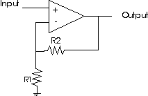
The op amp is so prevalent in electronics that it deserves it’s own symbol shown as the triangle in the schematic drawing. There are positive and negative inputs, an output pin. When there are no resistors connected to the op amp it outputs the voltage that is the difference between the + and – input voltages. This is called a comparator and can be very useful if a robot has sensors that are trying to see if one thing is “hotter”, “brighter”, “darker” etc. than some reference voltage.
With the resistors added the ouput voltage equals 1+ R1/R2. If the input voltage were 1.5 volts and the resistors were both 220 Ohms, what would the output voltage be?
Another common chip you’ll see in robots are Analog to Digital converters (A/D Converters). These devices take an analog signal from a sensor of light, temperature, sound etc. and turn it into a digital number that a computer can read. There are Digital/Analog converters too and they’re also used in robots but not as often as Analog to Digital. In order for the digital signal (remember that a digital number is a series of “1”s and “0”s) it must either be sent to the BASIC STAMPS’s input as a series of 1’s and 0’s on a single wire (we call this “serial input”) or on a bunch of wires each representing one place in the binary number system we learned about earlier (we call this “Parallel input”) These are used so often that most robotics microcontrollers have integrated the A/D converters for you.
A final typical chip you’ll be introduced to in robotics are voltage regulators. You will seldom see a robot that only uses one voltage for everything. Usually the motors have one voltage, the microcontroller has another and the mechanics for grabbing, throwing or other uses operate on a third voltage. Making sure you have enough of the right voltage is an important step in the design of your robot and you’ll want to make sure the voltage and current you supply is not too much and not too little for the task at hand.
Want to know more
http://www.youtube.com/watch?v=K03Rom3Cs28
https://learn.sparkfun.com/tutorials/analog-to-digital-conversion
http://www.youtube.com/watch?v=KZsyMnJ1NSs

Leave a comment